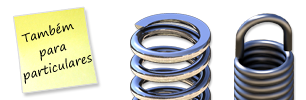
Compression Springs - Stainless Steel
Compression Springs | Produced In Stainless Steel

We offer a larger selection of compression springs produced in stainless steel here.
Find the correct dimensions by using the filters underneath. Open the filters by clicking the downward arrow.
If you know the stock-number, please write it in the search box at the top of the page.
See quantity discount by clicking on the green basket next to the item.
We can deliver within 24 hours, if you order before 15:45 from Monday till Thursday and before 14:30 on Fridays, if the item is in stock. Orders placed Saturday and Sunday are being shipped the following Monday.
| Ver preços - Adicionar ao carrinho | Material | d Diâmetro do arame (mm) |
De Diâmetro exterior (mm) |
Di Diâmetro interior (mm) |
Lo Comprimento livre (mm) |
Ln Comprimento máx. em carga (mm) |
Sn Curso máximo (mm) |
Fn Carga máxima em Ln (N) |
R Constante de mola (N/mm) |
Gama | REF | Stock | Desenho técnico | Ler mais | 3D CAD | |
|---|---|---|---|---|---|---|---|---|---|---|---|---|---|---|---|---|
| Aço inoxidável 302 | 0,80 | 10,00 | 8,40 | 50,00 | 16,30 | 33,70 | 11,93 | 0,35 | C | 512RF |

|

|
||||
| Aço inoxidável 302 | 0,90 | 9,00 | 7,20 | 25,00 | 16,09 | 8,91 | 7,40 | 0,83 | C | 513RF |

|
|
||||
| Aço inoxidável 302 | 1,00 | 16,00 | 14,00 | 75,00 | 16,37 | 58,63 | 15,20 | 0,26 | C | 520RF |

|
|
||||
| Aço inoxidável 302 | 1,25 | 14,00 | 11,50 | 75,00 | 27,62 | 47,38 | 30,52 | 0,64 | C | 515RF |

|
|
||||
| Aço inoxidável 302 | 1,50 | 12,00 | 9,00 | 22,00 | 11,80 | 10,20 | 78,05 | 7,65 | C | 514RF |

|
|
||||
| Aço inoxidável 302 | 1,50 | 14,50 | 11,50 | 17,00 | 7,55 | 9,45 | 76,23 | 8,07 | C | 511RF |

|
|
||||
| Aço inoxidável 302 | 1,70 | 14,70 | 11,30 | 27,00 | 14,51 | 12,49 | 75,57 | 6,05 | C | 518RF |

|
|
||||
| Aço inoxidável 302 | 2,00 | 16,00 | 12,00 | 80,00 | 34,51 | 45,49 | 178,53 | 3,93 | C | 517RF |

|
|
||||
| Aço inoxidável 302 | 2,00 | 20,00 | 16,00 | 85,00 | 36,98 | 48,02 | 85,39 | 1,79 | C | 519RF |

|
|
||||
| Aço inoxidável 302 | 2,50 | 17,30 | 12,30 | 20,00 | 12,92 | 7,08 | 271,30 | 38,34 | C | 516RF |

|
|
- 512RFEm stock: 1 283
Material Aço inoxidável 302d - Diâmetro do arame (mm) 0,80De - Diâmetro exterior (mm) 10,00Di - Diâmetro interior (mm) 8,40Lo - Comprimento livre (mm) 50,00Ln - Comprimento máx. em carga (mm) 16,30Sn - Curso máximo (mm) 33,70Fn - Carga máxima em Ln (N) 11,93R - Constante de mola (N/mm) 0,35Gama C
- 513RFEm stock: 1 190
Material Aço inoxidável 302d - Diâmetro do arame (mm) 0,90De - Diâmetro exterior (mm) 9,00Di - Diâmetro interior (mm) 7,20Lo - Comprimento livre (mm) 25,00Ln - Comprimento máx. em carga (mm) 16,09Sn - Curso máximo (mm) 8,91Fn - Carga máxima em Ln (N) 7,40R - Constante de mola (N/mm) 0,83Gama C
- 520RFEm stock: 1 840
Material Aço inoxidável 302d - Diâmetro do arame (mm) 1,00De - Diâmetro exterior (mm) 16,00Di - Diâmetro interior (mm) 14,00Lo - Comprimento livre (mm) 75,00Ln - Comprimento máx. em carga (mm) 16,37Sn - Curso máximo (mm) 58,63Fn - Carga máxima em Ln (N) 15,20R - Constante de mola (N/mm) 0,26Gama C
- 515RFEm stock: 1 448
Material Aço inoxidável 302d - Diâmetro do arame (mm) 1,25De - Diâmetro exterior (mm) 14,00Di - Diâmetro interior (mm) 11,50Lo - Comprimento livre (mm) 75,00Ln - Comprimento máx. em carga (mm) 27,62Sn - Curso máximo (mm) 47,38Fn - Carga máxima em Ln (N) 30,52R - Constante de mola (N/mm) 0,64Gama C
- 514RFEm stock: 388
Material Aço inoxidável 302d - Diâmetro do arame (mm) 1,50De - Diâmetro exterior (mm) 12,00Di - Diâmetro interior (mm) 9,00Lo - Comprimento livre (mm) 22,00Ln - Comprimento máx. em carga (mm) 11,80Sn - Curso máximo (mm) 10,20Fn - Carga máxima em Ln (N) 78,05R - Constante de mola (N/mm) 7,65Gama C
- 511RFEm stock: 1 144
Material Aço inoxidável 302d - Diâmetro do arame (mm) 1,50De - Diâmetro exterior (mm) 14,50Di - Diâmetro interior (mm) 11,50Lo - Comprimento livre (mm) 17,00Ln - Comprimento máx. em carga (mm) 7,55Sn - Curso máximo (mm) 9,45Fn - Carga máxima em Ln (N) 76,23R - Constante de mola (N/mm) 8,07Gama C
- 518RFEm stock: 396
Material Aço inoxidável 302d - Diâmetro do arame (mm) 1,70De - Diâmetro exterior (mm) 14,70Di - Diâmetro interior (mm) 11,30Lo - Comprimento livre (mm) 27,00Ln - Comprimento máx. em carga (mm) 14,51Sn - Curso máximo (mm) 12,49Fn - Carga máxima em Ln (N) 75,57R - Constante de mola (N/mm) 6,05Gama C
- 517RFEm stock: 543
Material Aço inoxidável 302d - Diâmetro do arame (mm) 2,00De - Diâmetro exterior (mm) 16,00Di - Diâmetro interior (mm) 12,00Lo - Comprimento livre (mm) 80,00Ln - Comprimento máx. em carga (mm) 34,51Sn - Curso máximo (mm) 45,49Fn - Carga máxima em Ln (N) 178,53R - Constante de mola (N/mm) 3,93Gama C
- 519RFEm stock: 1 629
Material Aço inoxidável 302d - Diâmetro do arame (mm) 2,00De - Diâmetro exterior (mm) 20,00Di - Diâmetro interior (mm) 16,00Lo - Comprimento livre (mm) 85,00Ln - Comprimento máx. em carga (mm) 36,98Sn - Curso máximo (mm) 48,02Fn - Carga máxima em Ln (N) 85,39R - Constante de mola (N/mm) 1,79Gama C
- 516RFEm stock: 3 765
Material Aço inoxidável 302d - Diâmetro do arame (mm) 2,50De - Diâmetro exterior (mm) 17,30Di - Diâmetro interior (mm) 12,30Lo - Comprimento livre (mm) 20,00Ln - Comprimento máx. em carga (mm) 12,92Sn - Curso máximo (mm) 7,08Fn - Carga máxima em Ln (N) 271,30R - Constante de mola (N/mm) 38,34Gama C
The wire is certified in accordance with DIN 17223 Class C Wire WERKSTOFF NO. 1.1200 – EN Norm 10270-1
Working temperature between -30 ºC and +120 ºC
Recommended for use in dry environments.
The wire is certified in accordance with DIN 17224 AISI 302 WERKSTOFF NO. 1.4310 – EN Norm 10270-3
Working temperature between -200 ºC and +250 ºC
Can be used in dry and humid or wet environments.
The wire is certified in accordance with DIN 17223 Class C Wire WERKSTOFF NO. 1.1200 – EN Norm 10270-1
Working temperature between -30 ºC and +120 ºC
Galvanised compression springs are made from piano wire, which is then electrogalvanised. Electrogalvanisation means that the compression spring is given a shiny, more corrosion-resistant surface.
Recommended for use in dry environments.
Series A and C: (See which series a spring belongs to in the “Series” column in the table. )
DIN 2098 defines the spring’s dimensions based on wire thickness.
DIN 2095 defines the force as the determining parameter. The number of coils will therefore vary. L0 is for guidance only and may well be longer than stated in the tables. Once loaded the spring will set itself and thus achieve the correct length. Deviations are usually observed with a large coil ratio ((De - d) / d), where the spring has a thin wire in relation to the diameter.
Mean diameter Tolerances
(mm)
(mm)
Coil ratio (Dm / d)
Series B: (See which series a spring belongs to in the “Series” column in the table.)
In this series, the number of coils is not specified, as the spring is produced with a defined unloaded length and a specific force. In order to achieve the forces, the number of coils will be the variable.
Series D: (See which series a spring belongs to in the “Series” column in the table. )
The series is produced for use in testing and prototyping. There are therefore no tolerances for this series. As this series is designed for testing, the cut spring’s coils will vary from spring to spring, and so the spring constant cannot be defined.
If you want a PDF datasheet or a 3D CAD drawing of the spring in .step, .iges or .sat format, these can be downloaded for free by clicking on the 3D CAD symbol next to the item number in the table.

If you want to know how much force a compression spring produces for a given length/travel, you can use the following formula:
Travel (s) x Spring constant ® (R)
If a spring is compressed 16 mm (s) and has a spring constant of 3 N/mm (R), this produces a force of: 16 mm x 3 N/mm = 48 N
16 mm x 3 N/mm = 48 N (ca. 4,8kg)
If a compression spring with a very high spring constant and carrying capacity is required, coloured die springs may be recommended. Read more
The spring constant tells you how much force a spring produces per millimetre when it is compressed. If a spring has a spring constant of 1.5 N/mm and it is compressed 10 mm, then the force of the spring is 15 N.
Series A, B and C: The spring constant is given in the table.
Series D: There are no spring constants for this range of springs. These springs are designed to test and try where the springs can be shortened to achieve the desired length. The spring constant depends on the length, so we are unable to provide a general spring constant.
Series A:
(See which series a spring belongs to in the “Series” column in the table. )
Springs with a wire thickness of up to 0.8 mm are closed but unground.
Springs with a wire thickness of 1.0 mm and above are closed and ground.
Series B and C:
(See which series a spring belongs to in the “Series” column in the table. )
The product page for each individual product shows if it is closed and ground or unground.
Series D:
(See which series a spring belongs to in the “Series” column in the table. )
As the series is produced for testing and cutting, the design of the ends is not defined.
Closed, ground
Closed, unground
Not closed
Usually right. The force and application is not affected by the direction of wind.
Standard compression springs are not defined with a specific direction of wind. Depending on production, the springs may be either right or left wound. If a specific direction of wind is required, it is possible to have them produced as special springs.
The service life of a spring is generally very difficult to define. A large number of parameters come into play, and it is therefore impossible to define a service life.
Parameters with a significant influence on service life include: Installation, installation method, number of movements, vibrations, shocks, torsion, length of travel, non-axial travel, temperature, wear against other surfaces, environment of use, any cleaning agents, lateral impacts, etc.
Always dimension a compression spring so that it delivers the desired travel and force with as little exertion as possible. This will give the spring the longest possible service life.
Applying the maximum load to the spring or exceeding it will shorten its service life and may cause it to become permanently distorted.
Therefore we recommend that you do not use more than 75% of the maximum travel (Sn) of conical springs.
If the compression spring is compressed to Ln (the max. loaded length), it will set itself. It will then not return to its original length.